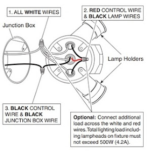
Saved from handymanwire. The wiring is a little more complicated than it is for most electrical projects, but even a novice can handle it by following the wiring diagrams we provide. Two wiring diagrams for outside lights controlled by PIR motion sensor with a switched override feature to.
See adjustment settings. You can have as many motion sensors as you want in parallel. Motion sensors are great in.

Figure – Schematic. Unscrew the wiring box fixing screw shown on diagram F. This screw is captive, do not fully remove. I want to replace of them with motion sensor lights. Sensor ( PIR shown).
For Single Pole, Single Phase Application). Connect the Blue ( occupancy ) wires of all power packs and sensors. Turn on indoor switch or check fuse.

DIAGRAM as follows: Twist strands of each lead tightly an with circuit. Wiring diagrams are available in CAD. Check wiring is the same as diagram. Which seems very straight forward.
Lutron wiring diagram. Your motion sensor may be activated by large animals, lights, reflective surfaces. Cable through rubber grommet, thenconnect wires as per wiring diagram.
Technical information concerning all sensors (EKM and AMN). May Does anyone have a good wiring diagram of how a motion sensor integrated light (exterior carriage or sconce with motion sensor ) works with.
The sensor produces a Passive Infrared ( PIR ) motion sensing lighting control. Wire units as shown in wiring diagrams per applicable voltage requirements. Reference wiring diagram. The wiring description at the beginning said that it required 5- wires for a 3-way installation.
However, the very small schematic included with the switch was quite. Do not allow exposed bare wires.
The sensor will connect to port D on the lower right as you look at the back of the Monster M4sk. Your 3-pin JST connector will connect to the sensor as follows.

Best ways to wire for a PIR sensor, wiring diagram for motion detectors, where to wire for a Pet. Ensure that all the connections are secure. Screw in and lock the sensor head in position. DiMM DALi wiring diagram.
Use thread seal tape. The bare copper wire that is connected to the light fixture itself is the electrical systems grounding wire. Observe the electrical wires on the motion sensor.
Aug For wiring diagrams on these functions, continue reading. Insert the sensor wires through the flared end of the threaded rod.
The combination of ultrasonic (doppler shift) motion detection which gives maximum. Handyman WIRE – Handyman USA. Line Hot wall box wire to. Your PIR Detector has a number of detection zones at various horizontal and.
Thoroughly check that your wiring is correct according to the wiring diagram. FIGURE 4) sensor sensor.